Tracii XL FAQs

I2C Vcc Resolution

The I2C API allows setting only arbitrary values for the I2C Vcc supply. Is it possible to set other values?
No, only the values 0V and 1.0V to 5.5V (100 mV resolution) can be set.

I2C Bus Capacity

Which capacity is added to the I2C bus by Tracii XL 2.0?
The typically capacity of Tracii XL 2.0 and telos I2C Negative Tester is < 80 pF.

Measure Termination

When measuring the internal termination of Tracii XL 2.0 using an ohmmeter, I do not see values, which have been configured in the GUI.
Due to the internal circuit you cannot measure the internal resistors using a ohmmeter. Instead measure the current between SCL/SDA and GND and use the I2C Vcc voltage to calculate the internal termination.

Registration Code Missing

I have bought a new Tracii XL 2.0 and have not received a registration code for my device. Where can I find my registration code?
You do not need a registration code for a new device. These codes are used only to unlock features, which you have bought later on.

Labview DLL

When using the I2C.Labview API Labview asks for the path of the i2capi_dotnet_labview.dll. Where can I find the DLL?
Normally Labview should find these DLLs automatically. There are stored in the Windows assembly caches. There is one assembly cache for .NET 2.0 and one for .NET 4.0.

Master Mode: High-Speed Token

When enabling the high-speed master mode of Tracii XL I can see transfers to an I2C slave with address 0x04. As there is no slave with such address on my I2C bus, these messages get no acknowledge. Who sends these messages to the I2C bus and why?
The I2C protcol specifies a high-speed token, which has to be sent to the I2C bus before going into high-speed mode. This token looks like “START, 0x08, NACK”. This token is sent to the I2C bus with a SCL clock up to 400 kHz. After this token the real high-speed transfer starts with a “RESTART”.

Master Transfer Seems To Be Stalled

If an I2C transfer is transmitted correctly but I2C studio gets stuck then it is often an electrical problem of the I2C bus. XL needs to trace its own data to recognize e.g. a stretching slave. But if the termination is too low or the thresholds are bad then the XL board could not “see” its own data which will lead to a “hanging” software. This problem can be solved by a decreasing the termination (I2C Studio: Options->Board) or by changing the thresholds to e.g. 40%/60% (I2C standard is 30%/70%).

I2C Speed Of Tracii XL

Under certain circumstances the I2C speed is lower than desired. This behaviour depends on the termination (pull-up resistor) and on the real capacitances of the I2C bus. If the termination is too high (e.g. 10k) and the capacitance on the bus is high too (e.g. > 200pF) this will lead to an increasing time of the rising edge on the SCL line and the high level on the bus will be achieved later. Hence the cycle duration will increase and the frequency will getting lower.
One solution is a lower termination to achieve the correct I2C speed (I2C Studio: Options->Board->Termination). 2kOhm could e.g. be a good choice for 5V I2C bus systems.

References

Capacitance versus I2C termination versus I2C speed at i2c-bus.org
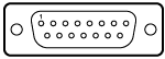
Windows Finds New Hardware But It Is Already Installed

Microsoft Windows, starting from Windows XP, will detect a new hardware if you just plug it into a different USB port on your computer.
This is normal, Microsoft decided to implement it this way. This means that you may have to go through the “Install Hardware Wizard” quite a few times if you have many USB ports and change your device.

What About The SUB-D Connector On XL

In addition to the PS/2 connector which should be used for I2C and test pin connection as the default connector, Tracii XL provides a SUB-D 15 connector for future extensions and special applications. We do not encurage users to make use of this connector in standard applications but since we receive so many questions about it we think it’s time to demystify those 15 magic pins.

SUB-D15 PIN Description
01 Testpin out 1
02 Testpin out 0
03 Testpin in 1
04 Testpin in 0
05 I2C-bus: SDA
06 I2C-bus: SCL
07 I2C-bus: GND
08 – 14 Reserved
15 I2C-bus: VCC

Note that I2C VCC needs to be supplied by the external I2C bus (1.2-6V) as a reference voltage.

But one secret remains: What are the reserved pins good for?

Tracii XL was designed as a future proof platform and as such it is equipped with various extra facilities for enhancements and custom applications. These may not even be I2C related but may include things like support of other bus systems, industrial automation control, event triggering etc. These future applications may show the need for additional connectors and we want to avoid modifications of the XL case for such purpose.

So, there are not only reserved pins visible on the outside – there is also more to come inside.

PS/2 (MiniDIN) Connector Pin Assignment


The pinning of the male telos I2C Connector

pin signal
1 SDA
2 Connii: reserved
Connii MM: TEST_OUT
Levii: TEST1
Optii: TEST_IN
Tracii XL: TEST_OUT
3 GND
4 VCC
5 SCL
6 Connii: reserved
Connii MM: TEST_IN
Levii: TEST2
Optii: TEST_OUT
Tracii XL: TEST_IN