
Tracer Time View
I2C Studio offers a detailed view of the timing of the traffic on an I2C bus/SMBus. The timing view can be seperated into three parts:
Byte Level
I2C Studio Time View
The byte level shows timing information about the elements, which have been transferred on an I2C bus/SMBus. The following elements get displayed:
- START/STOP conditions
- Data bytes
- ACK/NACK conditions
- I2C protocol errors
- SMBus power on/off
Even incomplete messages, e.g. those without a STOP condition are displayed.
Virtual Bit Level
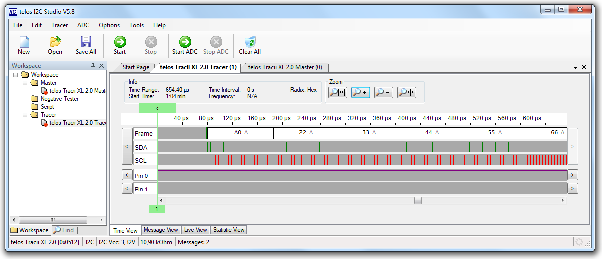
Tracer Bit Level
The virtual bit level gives an impression of how the transferred data would look like on an ideal I2C bus.
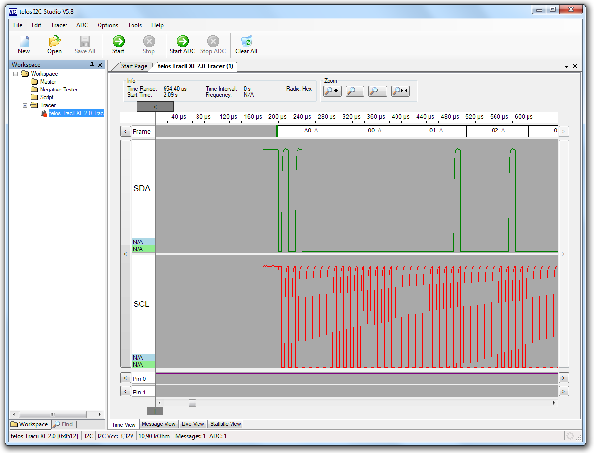
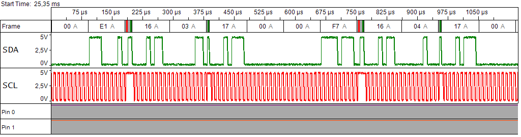
Electrical Level
During the development process the developer often needs to have a look at the eletrical layer of the I2C bus. The I2C bus has got several parameters like e.g. the bus termination or the cable capacitance, which the I2C bus has to fulfil to get a working setup. Adjusting these parameters is much easier, if the user has got a view of the eletrical level. Standard digital oscilloscopes come to their limitation if used for the I2C bus, because most of them cannot trigger on I2C conditions. The following features are available:
- configurable sampling rate
- configurable pretrigger (e.g. 0..50%)
- configurable trigger (e.g. START condition, STOP condition, ACK, NACK, and I2C error, address bytes and data bytes)
- automatic A/D restart
Input Testpins
Additional external digital signals can be monitored. This feature can be used in the SMBus mode to monitor the SMBus Alert and Suspend Lines.
Features
Other important features of the time view are:
- measurement: absolute time, time interval, frequency
- zoom: in, out, maximum, minimum, selected range
- jump buttons: next/previous message, next/previous A/D shot, next/previous testpin transition
- copy to clipboard (BMP)
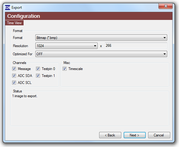
- export to file (BMP, TIFF)
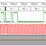
Time View Export Result
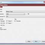
Time View Export Configuration
Supported I2C Products
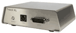 Tracii XL | 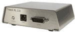 Tracii XL 2.0 |  Connii MM 2.0 |
 | |  |