Optii Functional Description
Internal Design
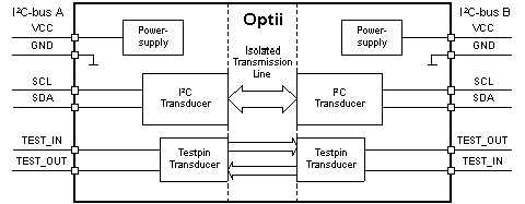
The main components of Optii are the bi-directional I2C transducer, the transducer for the test pins an the internal power supply as shown in Figure 1.

- Figure 1 Schematic Diagram
I2C Transducer
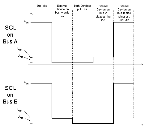
Optii uses different low-voltages to code and detect activities on the I2C lines. An internal reference voltage, called Uref, defines the threshold for this decision. While Optii’s own low-signal remains a voltage (Ulow) slightly higher than this reference voltage, external devices have to pull down the line lower than Uref. Only in this case, Optii transmits this signal to the other bus. This is done to maintain the bi-directional behavior in all cases of I2C transmissions.
The resulting voltages during an imaginary transfer on the SCL lines are shown schematically in Figure 2.

- Figure 2 Schematic Bus States
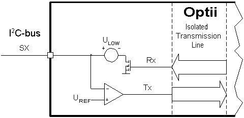
A more detailed view of one I2C-transducer is shown in Figure 3.
All four transducers are built analogically.

- Figure 3 Optiis I2C-Transducer
For proper operation both I2C buses have to be supplied via the appropriate Vcc line. Otherwise Optii pulls the I2C and testpin lines of the powered side low.
Due to the wide supply range, Optii automatically switches between two power-modes in dependency of the actual bus voltage (Vcc):
- High-Power Mode for 2.5 V to 5.5 V
- Low-Power Mode for 1.5 V to 2.5 V
The power-mode switching exhibits a hysteresis of about 600 mV. This means that Optii switches from the Low- to the High-Power Mode at a supply voltage of about 2.8 V and from High- to Low-Power Mode at a supply voltage of about 2.2 V.
Both modes cause different power consumption, reference voltages (Uref) and low-voltages (Ulow). The Electrical Specification contains detailed information about these values.
As a result of the function principle, Optiis do not transmit signals of other Optiis. This means that Optiis cannot be stacked.
Testpins
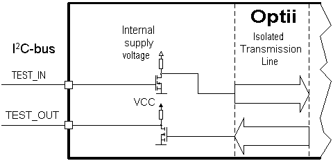
In addition to the I2C lines Optii offers two test pins for general purposes, one in each direction. These test pins are unidirectional signal lines. The inputs detect high level at about 0,85 V. The outputs are open-drain outputs pulled up by a 10 kOhm resistor.

- Figure 4 Test Pin Configuration
